How To Determine The Need For – And The Size Of – Compressed Air Receiver Tanks

Supply and Demand, in economics, defines the relationship between the volume of commodities that sellers want to exchange for a certain amount of currency, and the volume of said commodities that buyers are willing to exchange a certain (and sometimes different) amount of currency for.  The best chance for an ideal condition is when the volume produced is the same as the volume being consumed.  That typically means both sides are amenable to the same certain amount of currency, and everyone’s happy: the sellers are making a fair profit, and the buyers are paying a fair price.  Thing is, that’s a difficult balance to maintain.  The reasons for imbalances are often debated and usually contentious, and I have no intention of going in to them here.  I only brought up the subject to draw an analogy to the difficulties in maintaining a “supply and demand” balance in the design & operation of compressed air systems.

Just like in economics, we have to consider both sides – supply AND demand – to best maintain this balance.  Also like in economics, there are numerous factors…on both sides…but the two most critical factors are:

  • Compressor capacity control (supply side)
  • System storage (demand side)

My colleague Jordan Shouse wrote an excellent blog on “Air Compressor Motors and Controls, Working Together”, outlining the ‘supply side’ variables, allowing me to concentrate my efforts today on system storage. Distribution piping makes up a certain amount of this, and another great blog from another colleague, Tyler Daniel – “Intelligent Compressed Air: Distribution Piping and Pressure Drop” – gets me off the hook for THAT part of the discussion today.

We can consider the air capacity of system piping to be fixed for the purposes of this discussion, so our “variable” will be the capacity of storage tanks. Let’s start with the reasons for the need for system storage: Strategically placed point-of-use air receivers provide stored energy for intermittent demands.  This enables the compressed air system to handle fluctuating loads, efficiently & reliably.  It also minimizes impact (e.g., sudden and often detrimental drops) on the system pressure.

Next, we’ll look at location. There are a couple of common options to consider:

  • The intermittent demand. Installing a receiver here will provide enough air for short duration, high consumption events, protecting the rest of the system from pressure excursions. Dedicating the receiver to this application will mean isolating it from the rest of the system with a check valve (so it only supplies the load in question) and a needle valve (so recharging the receiver itself, between the intermittent uses, doesn’t adversely affect total system pressure).
  • The critical load(s). Instead of using stored air for the intermittent load, you can also use it for the important loads you’re trying to protect. All sorts of machinery with pneumatic components can “crash” if a nearby intermittent demand starts up & “steals” their air. You’ll use a check valve (same as above), but using a needle valve to throttle the air flow that recharges the receiver risks “starving” the critical load. Don’t do that unless there’s a really good (and likely really specific) reason for it.

Finally, we’re going to do some math, so we know how big this receiver has to be. Here’s the equation we use to do that:

Let’s calculate the receiver size needed to supply an intermittent load of 400 SCFM (C) @80psig (P2), that’ll run for one minute (T). You can use data specific to your system to come up with a value for (Cap) but here I’m going to assume we want the receiver to be able to handle the whole thing, so Cap = 0. I’m also going to assume we’re at sea level, so Pa = 14.7psia and that our compressor’s discharge pressure (the pressure at which the receiver can be charged to) is 120psig (P1):

That’s an awfully big tank. Now, let’s calculate the receiver size needed to protect a critical load that uses 55 SCFM @60psig, and that due to the system design, we can count on 25 SCFM @120psig from the compressor:

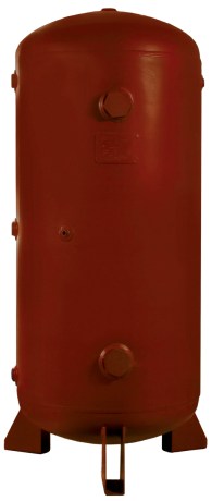
This is a much more manageable size, in fact, our 60 Gallon Receiver Tank (Model 9500-60) would be ideal. It’s 20″ in diameter and just over 50″ tall, so it doesn’t take up a lot of floor space. It comes with a drain valve and connections for compressed air flow in & out, pressure gauge, relief valve, etc.

Step Five of our Six Steps To Optimizing Your Compressed Air System: Use intermediate storage near the point of use.

Now, the above example is a completely hypothetical situation, and I purposely chose exaggerated values to show that there can indeed be a clear “winner” in the choice between the two installation points. “Your mileage may vary,” as the car folks say. If you have a situation like this, and would like help in finding the solution that makes the most sense, give me a call.

Russ Bowman, CCASS

Application Engineer
EXAIR Corporation
Visit us on the Web
Follow me on Twitter
Like us on Facebook

Cover image courtesy of: Tennessee Valley Authority; SVG version by Tomia, CC BY-SA 3.0 <http://creativecommons.org/licenses/by-sa/3.0/>, via Wikimedia Commons

Installing Secondary Receiver Tanks: Step 5 in Optimizing Your Compressed Air System

SixSteps

The 5th step in the 6 steps to optimizing your compressed air system highlights the use of intermediate storage of compressed air near the point of use. Secondary, or intermediate Receiver tanks are installed in the distribution system to provide a source of compressed air close to the point of use, rather than relying on the output of the compressor.

Compressed air receiver tanks are an integral part to many compressed air distribution systems. Compressed air is stored at a high pressure after drying and filtration, but just upstream of point of use devices. The receiver tank is charged to a pressure higher than what is needed by the system, creating a favorable pressure differential to release compressed air when needed.

Think of a compressed air receiver tank as a “battery”. It stores the compressed air energy within a system to be used in periods of peak demand, helping to maintain a stable compressed air pressure. This improves the overall performance of the compressed air system and helps to prevent pressure drop.

receiver_tank

They can be strategically placed to provide a source of compressed air to intermittent high volume compressed air applications. Rather than having to pull from the compressor, a receiver tank can be sized to provide the short-term volume of air for a particular application. In a previous post, we’ve highlighted how to calculate the necessary receiver tank based on the air consumption and duration of the application.

EXAIR offers from stock a 60-gallon receiver tank designed specifically for these higher-usage intermittent types of applications. Model 9500-60 can be installed near the point of high demand so that you have an additional supply of compressed air available for a short duration. The tank comes with mounting feet and is designed to stand up vertically, saving floor space. The tank meets American Society of Mechanical Engineers (ASME) pressure vessel code.

If you have an application in your facility that’s draining your compressed air system, a receiver tank could be the ideal solution. Give us a call and one of our Application Engineers will be happy to help evaluate your process and determine the most suitably sized receiver tank.

Tyler Daniel
Application Engineer
E-mail: TylerDaniel@EXAIR.com
Twitter: @EXAIR_TD

Receiver Tank Calculations

Receiver Tank

My colleague, Lee Evans, wrote a blog about calculating the size of receiver tanks within a compressor air system.  (You can read it here: Receiver Tank Principle and Calculations).  But, what if you want to use them in remote areas or in emergency cases?  During these situations, the air compressor is not putting any additional compressed air into the tank.  But, we still have potential energy stored inside the tanks similar to a capacitor that has stored voltage in an electrical system.  In this blog, I will show how you can calculate the size of receiver tanks for applications that are remote or for emergency systems.

From Lee Evans’ blog, Equation 1 can be adjusted to remove the input capacity from an air compressor.  This value is Cap below.  During air compressor shutdowns or after being filled and removed, this value becomes zero.

Receiver tank capacity formula (Equation 1)

V = T * (C – Cap) * (Pa) / (P1-P2)

V – Volume of receiver tank (cubic feet)

T – Time interval (minutes)

C – Air requirement of demand (cubic feet per minute)

Cap – Compressor capacity (cubic feet per minute)

Pa – Absolute atmospheric pressure (PSIA)

P1 – Tank pressure (PSIG)

P2 = minimum tank pressure (PSIG)


Making Cap = 0, the new equation for this type of receiver tank now becomes Equation 2.

Receiver tank capacity formula (Equation 2)

V = T * C * (Pa) / (P1-P2)

With Equation 2, we can calculate the required volume of a receiver tank after it has been pre-charged.  For example, EXAIR created a special Air Amplifier to remove toxic fumes from an oven.  The Air Amplifier was positioned in the exhaust stack and would only operate during power failures.  In this situation, product was being baked in an oven.  The material had toxic chemicals that had to cross-link to harden.  If the power would go out, then the product in the oven would be discarded, but the toxic fumes had to be removed.  What also doesn’t work during power outages is the air compressor.  So, they needed to have a receiver tank with enough volume to store compressed air.  From the volume of the oven, we calculated that they need the special Air Amplifier to operate for 6 minutes.  The compressed air system was operating at 110 PSIG, and the Air Amplifier required an average air flow of 10 cubic feet per minute from the range of 110 PSIG to 0 PSIG.  We are able to calculate the required receiver volume to ensure that the toxic fumes are evacuated from the oven in Equation 2.

Receiver tank capacity formula (Equation 2)

V = T * C * Pa / (P1 – P2)

V = 6 minutes * 10 cubic feet per minute * 14.7 PSIA / (110 PSIG – 0 PSIG)

V = 8 cubic feet.

Receiver tanks are more commonly sized in gallons.  In converting 8 cubic feet to gallons, we get a 60-Gallon Receiver Tank.  EXAIR recommended the model 9500-60 to be used near the oven to operate the special Air Amplifier during power outage.

Another way to look at Equation 2 is to create a timing equation.  If the volume of the tank is known, we can calculate how long a system will last.  In this example for scuba diving, we can use this information to configure the amount of time that a tank will last.  The diver has a 0.39 cubic feet tank at a pressure of 3,000 PSIG.  I will use a standard Surface Consumption Rate, SCR, at 0.8 cubic feet per minute.  If we stop the test when the tank reaches a pressure of 1,000 PSIG, we can calculate the time by using Equation 3.

Receiver tank timing formula (Equation 3):

T = V * (P1 – P2) / (C * Pa)

T – Time interval (minutes)

V – Volume of receiver tank (cubic feet)

C – Air demand (cubic feet per minute)

Pa – Absolute atmospheric pressure (PSIA)

P1 – Initial tank pressure (PSIG)

P2 – Ending tank pressure (PSIG)

By placing the values in the Equation 3, we can calculate the time to go from 3,000 PSIG to 1,000 PSIG by breathing normal at the surface.

T = 0.39 cubic feet * (3,000 PSIG – 1,000 PSIG) / (0.8 cubic feet per minute * 14.7 PSIA)

T = 66 minutes.

What happens if the diver goes into deeper water?  The atmospheric pressure, Pa, changes.  If the diver goes to 100 feet below the surface, this is roughly 3 atmospheres or (3 * 14.7) = 44.1 PSIA.  If we use the same conditions above except at 100 feet below, the time will change by a third, or in looking at Equation 3:

T = 0.39 cubic feet * (3,000 PSIG – 1,000 PSIG) / (0.8 cubic feet per minute * 44.1 PSIA)

T = 22 minutes. 

If you have any questions about using a receiver tank in your application, you can contact an EXAIR Application Engineer.  We will be happy to solve for the proper volume or time needed for your application.


John Ball
Application Engineer
Email: johnball@exair.com
Twitter: @EXAIR_jb

Receiver Tank Principle and Calculations

Hydroelectric_dam.svg

A receiver tank is a form of dry compressed air storage in a compressed air system.  Normally installed after drying and filtration, and before end use devices, receiver tanks help to store compressed air.  The compressed air is created by the supply side, stored by the receiver tank, and released as needed to the demand side of the system.

But how does this work?

The principle behind this concept is rooted in pressure differentials.  Just as we increase pressure when reducing volume of a gas, we can increase volume when reducing pressure.  So, if we have a given volume of compressed air at a certain pressure (P1), we will have a different volume of compressed air when converting this same air to a different pressure (P2).

This is the idea behind a receiver tank.  We store the compressed air at a higher pressure than what is needed by the system, creating a favorable pressure differential to release compressed air when it is needed.  And, in order to properly use a receiver tank, we must be able to properly calculate the required size/volume of the tank.  To do so, we must familiarize ourselves with the receiver tank capacity formula.

An EXAIR 60 gallon receiver tank

Receiver tank capacity formula

V = ( T(C-Cap)(Pa)/(P1-P2) )

Where,

V = Volume of receiver tank in cubic feet

T = Time interval in minutes during which compressed air demand will occur

C = Air requirement of demand in cubic feet per minute

Cap = Compressor capacity in cubic feet per minute

Pa = Absolute atmospheric pressure, given in PSIA

P1 = Initial tank pressure (Compressor discharge pressure)

P2 = minimum tank pressure (Pressure required at output of tank to operate compressed air devices)

An example:

Let’s consider an application with an intermittent demand spike of 50 SCFM of compressed air at 80 PSIG.  The system is operating from a 10HP compressor which produces 40 SCFM at 110 PSIG, and the compressed air devices need to operate for (5) minutes at this volume.

We can use a receiver tank and the pressure differential between the output of the compressor and the demand of the system to create a reservoir of compressed air.  This stored air will release into the system to maintain pressure while demand is high and rebuild when the excess demand is gone.

In this application, the values are as follows:

V = ?

T = 5 minutes

C = 50 CFM

Cap = 40 SCFM

Pa = 14.5 PSI

P1 = 110 PSIG

P2 = 80 PSIG

Running these numbers out we end up with:

This means we will need a receiver tank with a volume of 24.2 ft.³ (24.2 cubic feet equates to approximately 180 gallons – most receiver tanks have capacities rated in gallons) to store the required volume of compressed air needed in this system.  Doing so will result in a constant supply of 80 PSIG, even at a demand volume which exceeds the ability of the compressor.  By installing a properly sized receiver tank with proper pressure differential, the reliability of the system can be improved.

This improvement in system reliability translates to a more repeatable result from the compressed air driven devices connected to the system.  If you have questions about improving the reliability of your compressed air system, exactly how it can be improved, or what an engineered solution could provide, contact an EXAIR Application Engineer.  We’re here to help.

Lee Evans
Application Engineer
LeeEvans@EXAIR.com
@EXAIR_LE

Tennessee Valley Authority; SVG version by Tomia, CC BY-SA 3.0 <http://creativecommons.org/licenses/by-sa/3.0/>, via Wikimedia Commons