6 STEPS To Optimizing Compressed Air: Step 5 – Install Secondary Receiver Tanks

Since air compressors require electricity to make compressed air, it is important to optimize your compressed air system. EXAIR has six simple steps, and following these steps will help you cut electrical costs, reduce overhead, and improve your bottom line.  In this blog, I will cover the fifth step –intermediate storage of compressed air near the point-of-use. 

I had a customer that was looking at a model 1122108, 108” (2,743mm) Super Ion Air Knife Kit.  The application was removing static and debris from insulated panels which they used for large refrigerated trailers.  They were worried about how much compressed air that it would use; and they were considering a blower-type system.  I went through the negative aspects like noise, cost, maintenance, and ineffectiveness with turbulent air flows.  But, when you are limited in the amount of compressed air, I had to look at another way.  Since the process was intermittent, I used the fifth step to optimize their system to use a much better solution for their application.  The cycle rate was 2 minutes on and 10 minutes off.  I was able to calculate the size of a secondary tank to help their compressed air system.   

Model 9500-60

I would like to expand a bit more about secondary receiver tanks.  They can be strategically placed throughout the plant to improve the “ebbs and flows” of pneumatic demands.  The primary receiver tanks help to protect the supply side when demands are high, and the secondary receiver tanks help pneumatic systems on the demand side.  They give additional capacity at the end of distribution lines.  Essentially, it is easier and more efficient for compressed air to travel out from a nearby source and into an application rather than traveling through long lengths of pipes from the distribution system.

For calculating the volume size for your secondary receiver tank, we can use Equation 1 below.  It is the same for sizing a primary receiver tank, but the scalars are slightly different.  The supply line for air drops will typically come from a header pipe and are generally smaller in diameter.  So, we have to look at the air restriction that can feed into the tank.  For example, a 1” NPT Schedule 40 Pipe at 100 PSIG can supply a maximum of 150 SCFM of air flow.  This value is used for Cap below in Equation 1.  C is the largest air demand for the machine or targeted area that will be using the tank.  If the C value is less than the Cap value, then a secondary tank is not needed.  If the Cap is below the C value, then we can calculate the tank volume that would be needed.  The other value in the equation is the minimum tank pressure.  In most cases, a regulator is used to set the air pressure for the machine or area.  If the specification is 80 PSIG, then you would use this value as P2P1 is the header pressure that will be coming into the secondary tank.  With this collection of information, you can use Equation 1 to calculate the minimum tank volume. 

Equation 1:

V = T * (C – Cap) * (Pa) / (P1-P2)

Where:

V – Volume of receiver tank (cubic meter)

T – Time interval (minutes)

C – Air demand for system (cubic meter per minute)

Cap – Supply value of inlet pipe (cubic meter per minute)

Pa – Absolute atmospheric pressure (Bar)

P1 – Header Pressure (Bar)

P2 – Regulated Pressure (Bar)

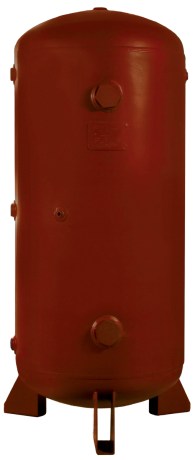
For this customer above, I am still working on this purchase.  But we went from a “we don’t have enough compressed air” to a “we can possibly use the better solution with the Super Ion Air Knife”.  If you find that you might be having issues with your equipment running optimally, you may be able to install a secondary receiver to your system.  EXAIR offers 60 Gallon tanks, model 9500-60, to add to those specific areas.  If you have any questions about using a receiver tank in your application, primary or secondary, you can contact an Application Engineer at EXAIR.

John Ball
Application Engineer
Email: johnball@exair.com
Twitter: @EXAIR_jb

How-To Size Receiver Tanks and Why Use Them in Your Compressed Air System

Receiver Tank

My colleague, Lee Evans, wrote a blog about calculating the size of primary receiver tanks within a compressed air system.  (You can read it here: Receiver Tank Principle and Calculations).  I would like to expand a bit more about secondary receiver tanks.  They can be strategically placed throughout the plant to improve the operation of your compressed air system.  The primary receiver tanks help to protect the supply side when demands are high, and the secondary receiver tanks help pneumatic systems on the demand side for optimum performance.

Circuit Board

I like to compare the pneumatic system to an electrical system.  The receiver tanks are like capacitors.  They store energy produced by an air compressor like a capacitor stores energy from an electrical source.  If you have ever seen an electrical circuit board, you notice many capacitors with different sizes throughout the circuit board (reference photo above).  The reason for this is to have a ready source of energy to increase efficiency and speeds with the ebbs and flows of electrical signals.  The same can be said for a pneumatic system with secondary receiver tanks.

To tie this into the compressed air system, if you have an area that requires a high volume of compressed air intermittently, a secondary receiver tank would benefit this type of pneumatic setup.  With valves, cylinders, actuators, and pneumatic controls which turn on and off, it is important to have a ready source of stored “energy” nearby.

For calculating a minimum volume size for your secondary receiver tank, we can use Equation 1 below.  It is the same for sizing a primary receiver tank, but the scalars are slightly different.  The supply line to this tank will typically come from a header pipe that supplies the entire facility.  Generally, it is smaller in diameter; so, we have to look at the air supply that it can feed into the tank.  For example, a 1” NPT Schedule 40 Pipe at 100 PSIG can supply a maximum of 150 SCFM of air flow.  This value is used for Cap below.  C is the largest air demand for the machine or targeted area that will be using the tank.  If the C value is less than the Cap value, then a secondary tank is not needed.  If the Cap is below the C value, then we can calculate the smallest tank volume that would be needed.  The other value in the equation is the minimum tank pressure.  In most cases, a regulator is used to set the air pressure for the machine or area.  If the specification is 80 PSIG, then you would use this value as P2P1 is the header pressure that will be coming into the secondary tank.  With this collection of information, you can use Equation 1 to calculate the minimum tank volume.  So, any receiver tank with a larger volume would work as a secondary receiver tank.

Equation 1:

V = T * (C – Cap) * (Pa) / (P1-P2)

Where:

V – Volume of receiver tank (cubic feet)

T – Time interval (minutes)

C – Air demand for system (cubic feet per minute)

Cap – Supply value of inlet pipe (cubic feet per minute)

Pa – Absolute atmospheric pressure (PSIA)

P1 – Header Pressure (PSIG)

P2 – Regulated Pressure (PSIG)

If you find that your pneumatic devices are lacking in performance because the air pressure seems to drop during operation, you may need to add a secondary receiver to that system.  EXAIR stocks 60 Gallon tanks, model 9500-60, to add to those specific areas.  If you have any questions about using a receiver tank in your application, primary or secondary, you can contact an EXAIR Application Engineer.  We can restore your efficiency and speed back into your applications.

John Ball
Application Engineer
Email: johnball@exair.com
Twitter: @EXAIR_jb

Photo: Circuit Board courtesy from T_Tide under Pixabay License

Why Start a Leak Prevention Program?

All compressed air systems will have some amount of leakage. It is a good idea to set up a Leak Prevention Program.  Keeping the leakage losses to a minimum will save on compressed air generation costs, and reduce compressor operation time which can extend its life and lower maintenance costs.

The Compressed Air Challenge estimates an individual compressed air leak can cost thousands of dollars per year when using $0.07/kWh.

  • 1/16″ diameter hole in excess of $700/year
  • 1/8″ hole in excess of $2900/year
  • 1/4″ hole in excess of $11,735 per year

There are generally two types of leak prevention programs:

  • Leak Tag type programs
  • Seek-and-Repair type programs

Of the two types, the easiest would be the Seek-and-Repair method.  It involves finding leaks and then repairing them immediately. For the Leak Tag method, a leak is identified, tagged, and then logged for repair at the next opportune time.

A successful Leak Prevention Program consists of several important components:

  • Document your Starting Compressed Air Use – knowing the initial compressed air usage will allow for comparison after the program has been followed for measured improvement.
  • Establishment of initial leak loss – See this blog for more details.
  • Determine the cost of air leaks – One of the most important components of the program. The cost of leaks can be used to track the savings as well as promote the importance of the program. Also a tool to obtain the needed resources to perform the program.
  • Find the leaks – Leaks can be found using many methods.  Most common is the use of an Ultrasonic Leak Detector, like the EXAIR Model 9061.  See this blog for more details. An inexpensive handheld meter will locate a leak and indicate the size of the leak.

    Model 9061
    Model 9061
  • Record the leaks – Note the location and type, its size, and estimated cost. Leak tags can be used, but a master leak list is best.  Under Seek-and-Repair type, leaks should still be noted in order to track the number and effectiveness of the program.
  • Plan to repairs leaks – Make this a priority and prioritize the leaks. Typically fix the biggest leaks first, unless operations prevent access to these leaks until a suitable time.
  • Record the repairs – By putting a cost with each leak and keeping track of the total savings, it is possible to provide proof of the program effectiveness and garner additional support for keeping the program going. Also, it is possible to find trends and recurring problems that will need a more permanent solution.
  • Compare and publish results – Comparing the original baseline to the current system results will provide a measure of the effectiveness of the program and the calculate a cost savings. The results are to be shared with management to validate the program and ensure the program will continue.
  • Repeat As Needed – If the results are not satisfactory, perform the process again. Also, new leaks can develop, so a periodic review should be performed to achieve and maintain maximum system efficiency.

An effective compressed air system leak prevention and repair program is critical in sustaining the efficiency, reliability, and cost effectiveness of an compressed air system.

If you have questions about a Leak Prevention Program or any of the 16 different EXAIR Intelligent Compressed Air® Product lines, feel free to contact EXAIR and myself or any of our Application Engineers can help you determine the best solution.

Jordan Shouse
Application Engineer
Send me an email
Find us on the Web 
Like us on Facebook
Twitter: @EXAIR_JS

Installing Secondary Receiver Tanks: Step 5 in Optimizing Your Compressed Air System

SixSteps

The 5th step in the 6 steps to optimizing your compressed air system highlights the use of intermediate storage of compressed air near the point of use. Secondary, or intermediate Receiver tanks are installed in the distribution system to provide a source of compressed air close to the point of use, rather than relying on the output of the compressor.

Compressed air receiver tanks are an integral part to many compressed air distribution systems. Compressed air is stored at a high pressure after drying and filtration, but just upstream of point of use devices. The receiver tank is charged to a pressure higher than what is needed by the system, creating a favorable pressure differential to release compressed air when needed.

Think of a compressed air receiver tank as a “battery”. It stores the compressed air energy within a system to be used in periods of peak demand, helping to maintain a stable compressed air pressure. This improves the overall performance of the compressed air system and helps to prevent pressure drop.

receiver_tank

They can be strategically placed to provide a source of compressed air to intermittent high volume compressed air applications. Rather than having to pull from the compressor, a receiver tank can be sized to provide the short-term volume of air for a particular application. In a previous post, we’ve highlighted how to calculate the necessary receiver tank based on the air consumption and duration of the application.

EXAIR offers from stock a 60-gallon receiver tank designed specifically for these higher-usage intermittent types of applications. Model 9500-60 can be installed near the point of high demand so that you have an additional supply of compressed air available for a short duration. The tank comes with mounting feet and is designed to stand up vertically, saving floor space. The tank meets American Society of Mechanical Engineers (ASME) pressure vessel code.

If you have an application in your facility that’s draining your compressed air system, a receiver tank could be the ideal solution. Give us a call and one of our Application Engineers will be happy to help evaluate your process and determine the most suitably sized receiver tank.

Tyler Daniel
Application Engineer
E-mail: TylerDaniel@EXAIR.com
Twitter: @EXAIR_TD