Does anyone else remember the episode of Friends where they were playing Pictionary and no one could guess what Monica was drawing? No, well, honestly, that’s the scene I thought of when looking at some system drawings for compressed air setups. If you need a refresher, see the YouTube clip below.
When trying to ensure you have a sustainable compressed air system within a facility, it is critical to ensure the layout is documented. This can be a very tedious task on existing systems that have been in place for years without any documentation, it doesn’t mean the idea should be lost. This can save considerable time and effort when looking at issues and or expansion of existing usage. The other point this can help greatly with is documenting and fixing leaks on your way to an optimized compressed air system.
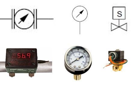
Along that same line, I’ve seen numerous reports over the past decade that all point to improperly maintained filter drains in compressed air systems that account for a large percentage of the 30% total system leakage that facilities can see. So I want to educate on the different types of P&ID symbols used for regulators and filters on compressed air systems so that our readers can better their preventive maintenance plans and install checkpoints at each one of these on a routine schedule.

If you are evaluating your compressed air system and trying to come up with a preventive maintenance plan, then each one of these symbols should be on a preventative check routine in order to ensure they are not a contributing factor to compressed air waste within your facility.
If you want to discuss other ways to optimize your compressed air system or other P&ID symbols used for pneumatic system components, reach out to any of the team here, and we will help you with your current situation.
Brian Farno, MBA – CCASS
National Business Development Manager

BrianFarno@EXAIR.com
@EXAIR_BF
1 – Friends, Pictionary|Friends – Retrieved from https://www.youtube.com/watch?v=yP2bX0ctoFs – published – 10/1/2023