The 5th step in the 6 steps to optimizing your compressed air system highlights the use of intermediate storage of compressed air near the point of use. Secondary, or intermediate Receiver tanks are installed in the distribution system to provide a source of compressed air close to the point of use, rather than relying on the output of the compressor.
Compressed air receiver tanks are an integral part to many compressed air distribution systems. Compressed air is stored at a high pressure after drying and filtration, but just upstream of point of use devices. The receiver tank is charged to a pressure higher than what is needed by the system, creating a favorable pressure differential to release compressed air when needed.
Think of a compressed air receiver tank as a “battery”. It stores the compressed air energy within a system to be used in periods of peak demand, helping to maintain a stable compressed air pressure. This improves the overall performance of the compressed air system and helps to prevent pressure drop.
They can be strategically placed to provide a source of compressed air to intermittent high volume compressed air applications. Rather than having to pull from the compressor, a receiver tank can be sized to provide the short-term volume of air for a particular application. In a previous post, we’ve highlighted how to calculate the necessary receiver tank based on the air consumption and duration of the application.
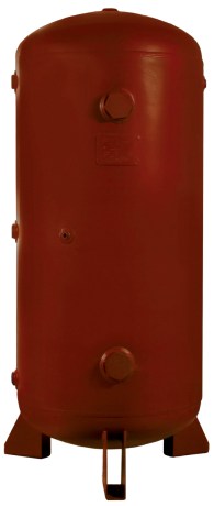
EXAIR offers from stock a 60-gallon receiver tank designed specifically for these higher-usage intermittent types of applications. Model 9500-60 can be installed near the point of high demand so that you have an additional supply of compressed air available for a short duration. The tank comes with mounting feet and is designed to stand up vertically, saving floor space. The tank meets American Society of Mechanical Engineers (ASME) pressure vessel code.
Just this past Spring, EXAIR hosted a live webinar where we discuss how to size, install, and implement secondary storage in your plant’s distribution system. If you missed it, check it out here on our website hosted by my colleague, Russ Bowman.
If you have an application in your facility that’s draining your compressed air system, a receiver tank could be the ideal solution. Give us a call and one of our Application Engineers will be happy to help evaluate your process and determine the most suitably sized receiver tank.
In any manufacturing environment, compressed air is critical to the operation of many processes. You will often hear compressed air referred to as a “4th utility” in a manufacturing environment. The makeup of a compressed air system is usually divided into two primary parts: the supply side and the demand side. The supply side consists of components before and including the pressure/flow controller. The demand side then consists of all the components after the pressure/flow controller.
The first primary component in the system is the air compressor itself. There are two main categories of air compressors: positive-displacement and dynamic. In a positive-displacement type, a given quantity of air is trapped in a compression chamber. The volume of which it occupies is mechanically reduced (squished), causing a corresponding rise in pressure. In a dynamic compressor, velocity energy is imparted to continuously flowing air by a means of impellers rotating at a very high speed. The velocity energy is then converted into pressure energy.
Still on the supply side, but installed after the compressor, are after coolers, and compressed air dryers. An after cooler is designed to cool the air down upon exiting from the compressor. During the compression, heat is generated that carries into the air supply. An after cooler uses a fan to blow ambient air across coils to lower the compressed air temperature.
When air leaves the after cooler, it is typically saturated since atmospheric air contains moisture. In higher temperatures, the air is capable of holding even more moisture. When this air is then cooled, it can no longer contain all of that moisture and is lost as condensation. The temperature at which the moisture can no longer be held is referred to as the dewpoint. Dryers are installed in the system to remove unwanted moisture from the air supply. Types of dryers available include: refrigerant dryers, desiccant dryers, and membrane dryers.
Also downstream of the compressor are filters used to remove particulate, condensate, and lubricant. Desiccant and deliquescent-type dryers require a pre-filter to protect the drying media from contamination that can quickly render it useless. A refrigerant-type dryer may not require a filter before/after, but any processes or components downstream can be impacted by contaminants in the compressed air system.
Moving on to the demand side, we have the distribution system made up of a network of compressed air piping, receiver tanks when necessary, and point of use filters/regulators. Compressed air piping is commonly available as schedule 40 steel pipe, copper pipe, and aluminum pipe. Some composite plastics are available as well, however PVC should NEVER be used for compressed air as some lubricants present in the air can act as a solvent and degrade the pipe over time.
Receiver tanks are installed in the distribution system to provide a source of compressed air close to the point of use, rather than relying on the output of the compressor. The receiver tank acts as a “battery” for the system, storing compressed air energy to be used in periods of peak demand. This helps to maintain a stable compressed air pressure. It improves the overall performance of the system and helps to prevent pressure drop.
Finally, we move on to the point-of-use. While particulate and oil removal filters may be installed at the compressor output, it is still often required to install secondary filtration immediately at the point-of-use to remove any residual debris, particulate, and oil. Receiver tanks and old piping are both notorious for delivering contaminants downstream, after the initial filters.
Regulator and filter
In any application necessitating the use of compressed air, pressure should be controlled to minimize the air consumption at the point of use. Pressure regulators are available to control the air pressure within the system and throttle the appropriate supply of air to any pneumatic device. While one advantage of a pressure regulator is certainly maintaining consistent pressure to your compressed air devices, using them to minimize your pressure can result in dramatic savings to your costs of compressed air. As pressure and flow are directly related, lowering the pressure supplied results in less compressed air usage.
EXAIR manufactures a wide variety of products utilizing this compressed air to help you with your process problems. If you’d like to discuss your compressed air system, or have an application that necessitates an Intelligent Compressed Air Product, give us a call.
Compressed air is used to operate pneumatic systems within a facility, and it can be separated into three categories; the supply side, the demand side, and the distribution system. The supply side is the air compressor, after-cooler, dryer, and receiver tank that produce and treat the compressed air. They are generally located in a compressor room somewhere in the corner of the plant. The demand side is the collection of devices that will use that compressed air to do “work”. These pneumatic components are generally scattered throughout the facility. To connect the supply side to the demand side, a compressed air distribution system is required. Distribution systems are pipes which carry the compressed air from the compressor to the pneumatic devices. For a sound compressed air system, the three sections have to work together to make an effective and efficient system.
An analogy that I like to use is to compare the compressed air system to an electrical system. The air compressor would be considered the voltage source, and the pneumatic devices would be marked as light bulbs. To connect the light bulbs to the voltage source, electrical wires are needed which will represent the distribution system. If the gauge of the wire is too small to supply the light bulbs, the wire will heat up and a voltage drop will occur. This heat is given off as wasted energy, and the light bulbs will be dim. The same thing happens within a compressed air system. If the piping size is too small, a pressure drop will occur. This is also wasted energy. In both types of systems, wasted energy is wasted money. One of the largest systematic problems with compressed air systems is pressure drop. If too large of a pressure loss occurs, the pneumatic equipment will not have enough power to operate effectively and efficiently. As shown in the illustration below, you can see how the pressure decreases from the supply side to the demand side. With a properly designed distribution system, energy can be saved; and, in referencing my analogy above, it will keep the lights on.
Pressure Drop Chart
To optimize the compressed air system, we need to reduce the amount of wasted energy. This can be caused from leaks or pressure drop. Leaks can be hidden and are typically located at connections within the distribution system. In a poorly maintained system, a study found that 30% of the compressor capacity is lost through air leaks on average. Even though leaks are the “silent killer” to a compressed air system, they can be found with the Ultrasonic Leak Detector.
Pressure drop is more of a wide range issue. It is based on restrictions, obstructions, and piping surface. Out of these, restrictions are the most common types of pressure drops. The air flow is forced into small areas, causing high velocities. The high velocity creates turbulent flow which increases the losses in air pressure. Flow within the pipe is directly related to the velocity times the square of the diameter. So, if you cut the I.D. of the pipe by one-half, the flow rating will be reduced by 25% of the original rating. Restriction type of pressure drop can be found in different forms like small diameter pipes or tubing; restrictive fittings like quick disconnects and needle valves, and undersized filters, regulators and valves.
As a rule, air velocities will determine the correct pipe size for the distribution system. It is beneficial to oversize the pipe to accommodate for any expansions in the future. For header pipes, the velocities should not be more than 20 feet/sec (6 meter/sec). For the distribution lines, the velocities should not exceed 30 feet/sec (9 meter/sec). In following these simple rules, the distribution system can effectively supply the necessary compressed air from the supply side to the demand side.
To have a properly designed distribution system, the pressure drop should be less than 10% from the reservoir tank to the point-of-use. By following the tips above, you can have the supply side, demand side, and distribution system working at peak efficiency. If you would like to reduce waste even more, EXAIR offers a variety of efficient, safe, and effective compressed air products to fit within the demand side. This will include the EXAIR Super Air Knives, Super Air Nozzles, and Safety Air Guns. This would be the pneumatic equivalent of changing those incandescent light bulbs into LED light bulbs. If you wish to go further in optimizing your system, an Application Engineer at EXAIR will be happy to help you.
An important step you must take after determining your compressed air requirements is the distribution piping for the system. The piping will be the “veins” that connect your entire facility to the compressor. Before installing pipe, it is important to consider how the compressed air will be consumed at the point of use. In order to ensure optimal performance of any compressed air operated device, you must ensure sufficient compressed air flow is delivered. Simply put, inadequate air flow won’t allow you to get the job done.
Pressure drop through the pipe is caused by the friction of the air mass making contact with the inside walls of the pipe. This is a function of the volume of flow through the pipe. Larger diameter pipes will result in a lower pressure drop, and vice versa for smaller diameter pipes. The chart below from the “Compressed Air and Gas Institute Handbook” provides the pressure drop that can be expected at varying CFM for 2”, 3”, and 4” ID pipe.
Once you’ve determined the appropriate piping size for your system, you’ll need to consider the different materials that are available. Some different materials that you’ll find as options are: steel piping (Schedule 40) both with or without galvanizing, stainless steel, copper, and even some plastic piping systems are available.
Plastic piping is not generally recommended to be used for compressed air. Some lubricants that are present in the air can act as a solvent and degrade the pipe over time. PVC should NEVER be used as a compressed air distribution pipe. Take a look at this inspection report an automotive supply store received fines totaling $13,200 as a result of an injury caused by shrapnel from a PVC pipe bursting. However, there are some composite plastics that are suitable for use with compressed air. PVC is most certainly not one of them.
Steel pipe is a traditional material used in many compressed air distribution systems. It’s strong and durable on the outside and is a familiar material for many to work with. Its strength comes at a price, steel pipe is very heavy and requires anchors to properly suspend it. Steel pipe (not galvanized) is also susceptible to corrosion. This corrosion ends up in your supply air and can wreak havoc on your point-of-use products and can even contaminate your product. While galvanized steel pipe does reduce the potential for corrosion, this galvanizing coating can flake off over time and result in the exact same potential issues. Stainless Steel pipe eliminates the corrosion and rusting concerns while still maintaining the strength and durability of steel pipe. They can be more difficult to install as stainless steel pipe threads can be difficult to work with
Copper piping is another potential option. Copper pipe is corrosion-free, easy to cut, and lightweight making it easy to suspend. These factors come at a significant increase in costs, however, which can prevent it from being a suitable solution for longer runs or larger ID pipe installations. Soldering of the connecting joints can be time consuming and does require a skilled laborer to do so.
Another lightweight material that is increasingly more common in industry is aluminum piping. Like copper, aluminum is lightweight and anti-corrosion. They’re easy to connect with push-to-lock connectors and are ideal for clean air applications. Aluminum pipe remains leak-free over time and can dramatically reduce compressed air costs. While the initial cost can be high, eliminating potential leaks can help to recoup some of the initial investment.
When designing and maintaining your compressed air system, pressure measurements should be taken across varying points to identify (and fix) any issues before they create a greater problem down the road. According to the Compressed Air Challenge, these are the places you should take regular pressure measurements to determine your system operating pressure:
Inlet to compressor (to monitor inlet air filter) vs. atmospheric pressure
Differential across air/lubricant separator
Interstage on multistage compressors
Aftercooler
At treatment equipment (dryers, filters, etc.)
Various points across the distribution system
Check pressure differentials against manufacturers’ specifications, if high pressure drops are noticed this indicates a need for service
*More recent compressors will measure pressure at the package discharge, which would include the separator and aftercooler.
Once you’ve taken these measurements, simply add the pressure drops measured and subtract that value from the operating range of your compressor. That figure is your true operating pressure at the point of use.
If your distribution system is properly sized and the pressure drops measured across your various equipment are within specifications, any pressure drop noticed at the point of use is indicative of an inadequate volume of air. This could be due to restrictive fittings or undersized air lines, hose, or tube. Check that the point of use product is properly plumbed to compressed air per the manufacturer’s specifications.
EXAIR Products are designed to minimize this pressure drop by restricting the flow of compressed air. The more energy (pressure) that we’re able to bring to the point of use, the more efficient and effective that energy will be. If you’re looking to improve on how compressed air is used within your manufacturing processes, give us a call.