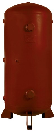
Secondary Receiver Tanks: Preparing for High-Demand Events.

Use intermediate storage near the point of use.

Secondary receiver tanks can be strategically placed throughout the plant to improve the “ebbs and flows” of pneumatic demands.  The primary receiver tanks help to protect the supply side when demands are high, and the secondary receiver tanks help pneumatic systems on the demand side.  The purpose of secondary air storage is for dedicated end-use systems or for additional capacity at the end of distribution lines.  Essentially, it is easier and more efficient for compressed air to travel from a nearby source rather than traveling through long lengths of pipe.  With any high-demand use equipment, it is beneficial to have additional storage installed nearby within the compressed air system.

For comparison, I would like to relate a pneumatic system to an electrical system.  The receiver tanks would be like capacitors.  They store pressurized air like a capacitor stores energy from an electrical source.  If you have ever seen an electrical circuit board, you will notice many capacitors of different sizes throughout the circuit board.  The reason for this is to have a ready source of energy to increase efficiency and speeds with the ebbs and flows of electrical signals.  The same can be said for a pneumatic system with secondary receiver tanks.

To cover a current application, I had a customer that was looking at a model 1122108; 108” (2,743mm) Gen4 Super Ion Air Knife Kit.  The application was to remove static and debris from insulated panels for large refrigerated trailers.  They were worried about how much compressed air it would use, and they were considering a blower-type system.  I went through the negative aspects of blower-type systems, like loud noise levels, capital expense, high maintenance cost, large footprint, and ineffectiveness with turbulent air flows.  But, when you are limited to the amount of compressed air, it may seem difficult to get the best product for your application.  Looking at it another way, I asked him if the process was intermittent; and it was.  The cycle rate was 2 minutes on and 10 minutes off.  I was able to recommend a secondary tank to help ease the high demand for their compressed air system.

To calculate the volume size of your secondary receiver tank, we can use Equation 1 below.  It is the same for sizing a primary receiver tank, but the scalars are slightly different.  The supply line to this tank will typically come from a header pipe that supplies the entire facility.  Generally, it is smaller in diameter, so we have to look at the air supply that it can feed into the tank.  For example, a 1” NPT Schedule 40 pipe at 100 PSIG (7 bar) can supply a maximum of 150 SCFM (255 M3/hr) of air flow.  This value is used for Cap below.  The C value is the largest air demand for the machine or equipment that will be using the tank.  If the C value is less than the Cap value, then a secondary tank is not needed.  If the Cap is below the C value, then we can calculate the smallest tank volume that would be needed.  The other value in the equation is the minimum tank pressure.  In most cases, a regulator is used to set the air pressure for the machine or area.  If the specification is 80 PSIG (5.5 bar), then you would use this value as P2P1 is the header pressure that will be coming into the secondary tank.  With this collection of information, you can use Equation 1 to calculate the minimum tank volume. 

Equation 1:

V = T * (C – Cap) * (Pa) / (P1-P2)

Where:

V – Volume of receiver tank – Imperial (ft3) or SI (M3)

T – Time interval (minutes)

C – Air demand for system – Imperial (SCFM) or SI (M3/min)

Cap – Supply value of inlet pipe – Imperial (SCFM) or SI (M3/min)

Pa – Absolute atmospheric pressure – Imperial (PSIA) or SI (Bar)

P1 – Header Pressure – Imperial (PSIG) or SI (Bar)

P2 – Regulated Pressure – Imperial (PSIG) or SI (Bar)

In many cases, you can also lengthen the time to refill the secondary receiver by restricting the refill rate with a valve, so that it is more of a constant, but much lower draw on the compressor system. This technique also helps to diminish the impact of the large-use items attached to a customer’s system.

For the customer above, I am still getting more details about their system before we finalize on a solution.  But the important point in utilizing this concept is that we went from a “we don’t have enough compressed air” to a “we can use a better solution with the Super Ion Air Knife” and here’s how.

If you find that your compressed air system needs a boost for your pneumatic process, we may be able to recommend a secondary receiver tank for your system.  EXAIR does offer 60-gallon tanks, model 9500-60, to add to those specific areas.  If you have any questions about using a receiver tank in your application, you can contact an Application Engineer at EXAIR.  We will be happy to help. 

John Ball
Application Engineer
Email: johnball@exair.com
Twitter: @EXAIR_jb

Compressed Air System Optimization – Where Do Receiver Tanks Fit?

SixSteps

The 5th step in the 6 steps to optimizing your compressed air system highlights the use of intermediate storage of compressed air near the point of use. Secondary, or intermediate Receiver tanks are installed in the distribution system to provide a source of compressed air close to the point of use, rather than relying on the output of the compressor.

Compressed air receiver tanks are an integral part to many compressed air distribution systems. Compressed air is stored at a high pressure after drying and filtration, but just upstream of point of use devices. The receiver tank is charged to a pressure higher than what is needed by the system, creating a favorable pressure differential to release compressed air when needed.

Think of a compressed air receiver tank as a “battery”. It stores the compressed air energy within a system to be used in periods of peak demand, helping to maintain a stable compressed air pressure. This improves the overall performance of the compressed air system and helps to prevent pressure drop.

receiver_tank

They can be strategically placed to provide a source of compressed air to intermittent high volume compressed air applications. Rather than having to pull from the compressor, a receiver tank can be sized to provide the short-term volume of air for a particular application. In a previous post, we’ve highlighted how to calculate the necessary receiver tank based on the air consumption and duration of the application.

EXAIR offers from stock a 60-gallon receiver tank designed specifically for these higher-usage intermittent types of applications. Model 9500-60 can be installed near the point of high demand so that you have an additional supply of compressed air available for a short duration. The tank comes with mounting feet and is designed to stand up vertically, saving floor space. The tank meets American Society of Mechanical Engineers (ASME) pressure vessel code.

Just this past Spring, EXAIR hosted a live webinar where we discuss how to size, install, and implement secondary storage in your plant’s distribution system. If you missed it, check it out here on our website hosted by my colleague, Russ Bowman.

If you have an application in your facility that’s draining your compressed air system, a receiver tank could be the ideal solution. Give us a call and one of our Application Engineers will be happy to help evaluate your process and determine the most suitably sized receiver tank.

Tyler Daniel, CCASS
Application Engineer
E-mail: TylerDaniel@EXAIR.com
Twitter: @EXAIR_TD

Which Condensate Drain Is Best For Your Compressed Air System?

In a perfect world, your air compressor’s intake would be free of dirt, oil, and water. Proper maintenance (i.e., periodic cleaning and/or changing) of the intake filter will keep most of the dirt out. Oil and water vapor will pass right through…but that’s not the end of the world (however imperfect it may be); they’re easy to take care of later in the process.

Once these vapors have been compressed (along with all that air that was drawn in), it’ll go into the receiver (usually via an aftercooler in industrial compressors) where it cools down, and that vapor condenses. If it’s left alone, a couple of things can happen:

  • Standing water in the bottom of a steel tank will cause corrosion. This can be carried into your compressed air distribution system. Over time, it will also rust through the reservoir. You don’t want either of these things to happen.
  • Eventually, it’ll take up enough space that your reservoir’s capacity will effectively shrink. That can cause your compressor to cycle rapidly. You don’t want that either.

Even the smallest of compressors will have manual drain valves on the bottoms of their reservoirs. Users will simply blow down the gallon or so tank every so often and go about their business. The small amount of electrical power that the compressor will use to recharge those tanks makes this a perfectly acceptable practice.

In the perfect world I mentioned above, the large reservoirs on industrial air compressors could be drained of condensate in the same manner. There are a few challenges to periodic manual draining:

  • You could do it on a schedule, but varying levels of humidity mean different accumulation rates of condensation. Weekly blowdowns might be OK in the winter, but you may need to do it daily in the summer. And a couple days a week in the spring or fall. It can be a real chore to keep track of all of that.
  • A practiced operator may develop the skill to shut the valve immediately upon the last drop of condensate passing. More often than not, though, you’re going to lose some compressed air doing it manually.
  • File this under “don’t try this at home (or anywhere, really)” – an unfortunately all-too-common practice is to just leave a manual drain cracked open. It works, but it wastes compressed air. On purpose. There’s too much accidental waste to give this any further discussion. Just don’t do it.
  • Plain old forgetfulness, someone going on vacation, or even leaving the company could result in someone else noticing the compressor is frequently cycling (because the reservoir is filling with water…see above), and realizing nobody’s drained the tank in a while.

Again, these manual drains are quite common, especially in smaller air compressor systems…and so are the above challenges. I may or may not have personal experience with an incident similar to that last one. Good news is, there are automated products designed to prevent this from happening to you:

  • Timer drains are popular and inexpensive. They operate just as advertised: a programmable timer opens and closes the drain valve just like you tell it to. They don’t do anything at all to address the first two challenges above: they might blow down for longer than needed (and waste compressed air) or not long enough (and allow water to build up in the reservoir.) They come in two primary configurations:
    • Solenoid Valve: the timer energizes the valve’s coil to open the valve, and a spring shuts it when the timer runs out. Strainers will prevent blockage, and will need periodic maintenance.
    • Ball Valve: the timer operates an electric actuator to open & close the valve. The full port opening of the ball valve means a strainer is usually not necessary, so these are less maintenance intensive.
  • Demand (AKA “no waste” or “zero loss”) drains are actuated by the condensate level in the reservoir. They don’t discharge any of the reservoir’s compressed air, because they close before the last bit of water exits. There are a few common options to choose from:
    • Mechanical float drains can be internal or external…the latter is more common for use with air compressor reservoirs; the former is fairly standard with point-of-use filters (more on that later). When the liquid level rises, the float opens the drain; when liquid level drops, the float closes the drain…easy as that. They CAN be susceptible to clogging with debris, but many have screens to prevent or limit that.
    • Electronic types use a magnetic reed switch or capacitance device to sense the condensate level…so they require electric power.
    • These cost more than the timer types, though, and they’ve got a number of moving parts, so they can find themselves in need of repair. Inexpensive and user-friendly rebuild kits are oftentimes available, and many of these come with alarms to let you know when to use that rebuild kit.

Whether you have a manual, timer, or demand drain, keep in mind that some moisture can still be carried over, and rust/scale can still form in pipelines. Good engineering practice calls for point-of-use filtration, like EXAIR’s Automatic Drain Filter Separators and Oil Removal Filters. If you’d like to talk more about getting the most out of your compressed air system, give me a call.

Russ Bowman, CCASS

Application Engineer
EXAIR Corporation
Visit us on the Web
Follow me on Twitter
Like us on Facebook

Intermediate Storage Tanks & How To Size Them

When evaluating processes that utilize compressed air and adhering to the Six Steps to Compressed Air Optimization, intermediate storage proves to be a critical role coming in at step number five. Intermediate storage tanks may already be in place within your facility and often times can be implemented as modifications to aid existing lines that are struggling to maintain proper availability of compressed air to keep the line at peak performance.

EXAIR Receiver Tank in 60 Gallon Capacity

When determining whether or not a production line or point of use compressed air operation would benefit from a receiver tank/intermediate storage we would want to evaluate whether the demand for compressed air is intermittent.  Think of a receiver tank as a capacitor in an electrical circuit or a surge tank in a water piping system.  These both store up energy or water respectively to deliver to during a short high demand period then slowly charge back up from the main system and prepare for the next high demand.   If you look from the supply point it will see a very flattened demand curve, if you look from the application side it still shows a wave of peak use to no use.

Intermittent Applications are prime for rapid on/off of compressed air.

One of the key factors in intermediate storage of compressed air is to appropriately size the tank for the supply side of the system as well as the demand of the application.  The good news is there are equations for this.  To determine the capacity, use the equation shown below which is slightly different from sizing your main compressed air storage tank.  The formulate shown below is an example.

Where:

V – Volume of receiver tank (ft3 / cubic feet)

T – Time interval (minutes)

C – Air demand for system (cubic feet per minute)

Cap – Supply value of inlet pipe (cubic feet per minute)

Pa – Absolute atmospheric pressure (PSIA)

P1 – Header Pressure (PSIG)

P2 – Regulated Pressure (PSIG)

One of the main factors when sizing point of use intermediate storage is, they are being supplied air by smaller branch lines which cannot carry large capacities of air.  That limits your Cap value. The only way to decrease the V solution is to increase your Cap. The other key point is to ensure that all restrictions feeding into the tank and from the tank to your point of use are minimized in order to maintain peak performance.

If there are intermittent applications that are struggling to keep up with the production demands within your system, please reach out and speak with an Application Engineer.  We are always here to help and we may even be able to help you lower the demand needed by utilizing an engineered point of use compressed air solution.

Brian Farno
Application Engineer
BrianFarno@EXAIR.com
@EXAIR_BF